| Introduction to 3-D |
| |
| Creating New Materials |
| |
| Once you start working with AutoCAD's materials, you'll soon realize that you don't really have a large selection. What is you need a white stucco material for a wall? Or grass for the lawn, or brushed aluminum, or... well, you get the picture. What you need to do is create your own materials. |
| |
| But what if want something totally different? Then you have to make a new material. |
| |
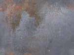
| The first step is to locate an image that represents the material you want in your drawing. There are a number of sources available on the internet. Check out the links page for some. Below are 3 samples you can try for this lesson. |
| |
| Metal Sample |
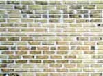
Brick Sample |
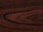
Wood Sample |
 |
 |
 |
|
| |
| Pick on any of the images above and when the new window opens, right click on the large image and select "Save image as..." and save it in a folder where you can find it easily. |
| |
| Now start the MATERIALS command to open the Materials Palette. |
| |
 |
At first glance, this will look very different if you are used to previous versions of AutoCAD. If you have used 3D Studio MAX, then it may look familiar.
Palettes are used in AutoCAD in much the same way as dialog boxes. A big difference is that they can be left on the screen while you are drawing. You can expand or collapse a palette by clicking the < or > buttons on the bottom left. Close it by clicking the X on the top left corner.
In the top section of the palette is the materials used in the drawing shown as balls in default view. Below are buttons you will be using to work with the material, and at the bottom is a section for editing the material.
I will take you through the simple process of creating a material from an image file and applying it to an an object in your drawing. Then you will learn how to modify the material.
Other lessons will give you more information on mapping the material to an object. |
|
| |
To create a new material from one of the images from above (or another texture) open the materials palette and click New Material button . This will open a dialog for naming. . This will open a dialog for naming. |
| |
 |
| |
| Give it a good name and description (start with good habits) and press OK. Now you are back in the Materials Palette. Click on the Select button in the Diffuse map section: |
| |
 |
| |
| You should notice a new ball in the top section that has the material mapped to it. The clarity of the material will depend on it's contrast in the image and the size of the ball in the top section. |
| |
Now is the east part. Draw a solid object of some kind. Highlight your new material by clicking on the ball. Next click the Apply Material to Object button . Finally, select the object. . Finally, select the object. |
| |
| If everything looks right, great. If not, you may have to use the mapping tools you learned to adjust the material to your liking. |
| |
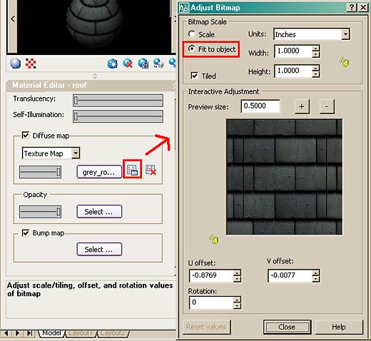
| Another option to get the materials set in scale to the object is to use the "Scale to Object" setting in the Materials Palette. This is found after you have created a new material next to the Select... button which will open up the Adjust Bitmap dialog (formally found in the SETUV command). |
| |
 |
| |
| This will help get the scale close to what you want it to be, of course this depends on the size of your original image file (as a rule, larger files are better as you can scale them down and retain clarity). This dialog box also allows for more settings, but each will apply to your own specific needs and image files. Try different settings and check the results. |
| |
| To make the material transparent or translucent, move the opacity slider on the Materials Palette to about 50 - making the material 50% transparent. You can adjust other options as shown in this dialog box. |
| |
| This is just an introduction to the world of creating new materials. If you have a photo editing program like Photoshop, Gimpshop (it's free) or another, you will be able to adjust the image files to fit your needs. |
| |
| There is only one way to get better at AutoCAD and that is to practice. In 3D, you not only need to know the commands, but also how best to use them. As you start drawing in 3D, you may start looking at everyday objects and think about how they would be drawn. Look at the sample drawing page and think about how they were done - using only the commands shown in this level. |
| |
| Creating A 3d Object From A 2d Profile |
| |
| For this tutorial, you should be familiar with these commands: region, extrude, union, subtract. |
| |
| This tutorial shows you a method for quickly turning 2D shapes into 3D objects. One of biggest problems with 2D objects is that they are not always drawn properly. This is something that should have been addressed when it was first drawn, but here is a way of working around it. |
| |
| First lets start with a basic shape. This is the profile for a gasket. It is drawn in 2D with lines, arc and circles. |
| |
 |
| |
| |
| If it was well drawn, meaning no overlapping lines, gaps, etc. Here is how you do it. Start the REGION command. Draw a crossing window around the whole area and press enter. Once you have your regions created, you can extrude them. Start the EXTRUDE command and select all objects. Press enter and enter your extrusion height and taper angle. When these are extruded, begin your SUBTRACT command and first select the larger object first (to be subtracted from), press enter then select all the other objects and press enter. When you change to your SW Isometric view, type in HIDE (enter) and you should see the object as shown below. |
| |
 |
| Remember that you can always work in your SW Isometric view to see the progress of your 3D work. |
| |
| There is one problem when using the REGION command. If have two lines that are overlapping, AutoCAD can not make a region out of the objects. You could search until find the offending line, but there is an easier way. Here's this approach: |
| |
| Instead of using the region command, use the BPOLY command. This command works similar to the HATCH command in that it finds the boundaries for you. Start the command and you will see this dialog box come up: |
| |
 |
| |
| Accept the defaults and press on the Pick Points< button. In your drawing screen, pick an internal point as if you were hatching it and then press enter. |
| |
| Now start your EXTRUDE command and select the last (L) object created and extrude it. Now begin the SUBTRACT command and select the outside object, (press enter) then use a crossing box to select everything else and press enter. Use the HIDE command to ensure that everything is as it should be. |
| |
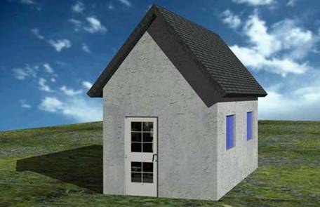
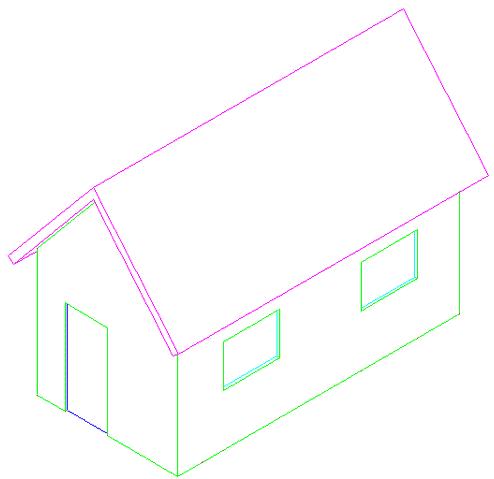
| If you have completed the previous lessons in this level, you now have the tools to create a large variety of objects in 3D. This lesson is designed to show how to create simple building in 3D from start to finish. |
| |
| Below is an image of the final building that is explained in this lesson. |
| |
 |
| |
| Start by setting your units to architectural (DDUNITS). Remember to create new layers for each type of objects you will draw (windows, doors, walls, roof, etc). Also use the "View > Visual Styles > Realistic" option when adding materials. |
| |
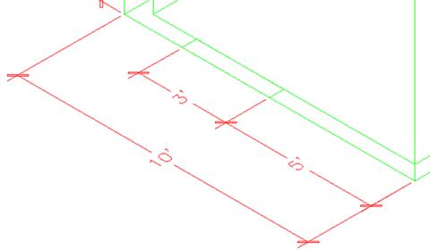
| Now draw the bases of the walls using the dimensions are shown below. You don't need to dimension it. Optionally, you can use the (new in AutoCAD 2007) POLYSOLID command. |
| |
 |
| Now you will create regions out of all your wall lines. |
| |
Command: REG <ENTER> REGION
Select objects: <SELECT ALL THE LINES> Specify opposite corner: 7 found |
| |
Select objects: <ENTER>
3 loops extracted.
3 Regions created. |
| |
| You should now have 3 regions. If you don't then it usually means the your lines don't meet. |
| |
| Next you are going to EXTRUDE the walls 9' high. |
| |
Command: EXT <ENTER> EXTRUDE
Current wire frame density: ISOLINES=4
Select objects: <SELECT THE 3 REGIONS> Specify opposite corner: 3 found
Select objects:
Specify height of extrusion or [Path]: 9' <ENTER>
Specify angle of taper for extrusion <0>: <ENTER> |
| |
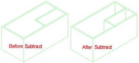
| It should appear that nothing has happened. You will need to go to the SW Isometric view to see how the wall were extruded. Do this and then use the HIDE Command. Something doesn't look right. What you will need to do is Subtract the 2 smaller regions from the larger region. You should see this result after the Subtract and Hide commands. |
| |
 |
| |
| Now it's starting to look like something. Your walls are almost complete. |
| |
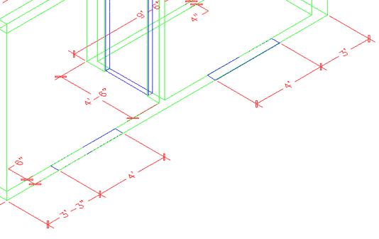
| Next you will add a door or two. The first door, on the outside will be on the bottom left wall. Start by drawing a rectangle from the middle of the outside wall and the other corner @6,36 - this will create the opening. Your rectangle should look like this: |
| |
 |
| |
| Now you want to EXTRUDE the rectangle up 6'8" and SUBTRACT it from the wall. |
| |
| Create a door layer (or make it active if you already have one) and draw a rectangle in the door opening that is 3"x 3' - put it in the middle of the door opening. Extrude it 6'8". |
| |
| Now create a second door (and opening) on the inside wall parallel to the outside wall that is 32" wide. After you do that, the drawing should look like this from the SW Isometric view: |
| |
 |
| If you haven't saved your drawing yet, now would be a good time. |
| |
| Now you're going to add some windows. This will be done using a similar process as the door. You will create openings, then add the window. |
| |
| Create 2 rectangles in the position shown below. |
| |
 |
| EXTRUDE the window 36 inches. Them move them up 3'8" in the Z axis |
| |
Command: M
MOVE
Select objects: 1 found
Select objects: 1 found, 2 total
Select objects: Specify base point or displacement: <PICK ANYWHERE ON SCREEN>
Specify second point of
displacement or <use first point as displacement>: @0,0,3'8 |
| |
| Now mirror the bottom left box to the opposite wall (Note: It will be easier if you revert to the top view for the mirror command)and the upper box to the inside wall so you have the 4 boxes looking like this : |
| |
 |
| Next, subtract the four window openings from the walls. After switching to SW Isometric view and using the hide command, your drawing should look like this: |
| |
 |
| |
| Now the window panes have to go in. Since this is a simple drawing, you just be putting in a plane of glass to represent the window. |
| |
| Create a new layer for windows. The easiest way to do this is just like you created the doors. Make the window 1" deep. Once again, start with the rectangle at the base of the window opening, extrude it the height of the window opening and move it into the centre. |
| |
| Once you have one window made, copy it to the other openings. Save your drawing and then type in SHADE and choose the G option. Your building should look like this: |
| |
 |
| Wow - now you're getting there. Next you will add to the walls to make them the right pitch for the roof. |
| |
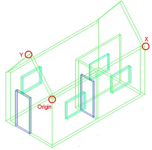
| First you will have to change your UCS. Start the UCS command and choose the 3Point option by typing 3 <ENTER>. When prompted (watch the command line) select the points shown below: |
| |
 |
| After you pick the third point, the cursor should turn on its side. Now you can draw on the side of the building. In this case, you will be drawing a triangular shape to represent the rest of the wall up to the roof. |
| |
| Draw a LINE from the middle of the top outside of the wall up 6'. Then draw a POLYLINE from one corner, to the next, to the top of the line and use the C option to close the polyline. |
| |
| Finally EXTRUDE the triangle -6" and then COPY the extruded object to the other side of the building. Erase the vertical line you drew. You should have something like this now: |
| |
 |
| |
| To finish the wall, perform a UNION between the triangular sections and the bottom wall. |
| |
| You're almost done now. You will need to draw the roof to complete the drawing. |
| |
| First you will need to change your UCS to align it with the slant of the roof. Use the points shown below - and be careful which endpoints you select. |
| |
 |
| Now draw a RECTANGLE from the top left corner of the triangular shape to the bottom of the opposite corner of the other triangular shape. It should like the magenta rectangle below: |
| |
 |
| New EXTRUDE the rectangle 6". Then copy 12" down in the Y Axis and then copy it 12" up in the Y Axis - when you have the 3 sections UNION them into one object. |
| |
| Change back to the WCS (UCS <ENTER><ENTER>) and mirror the roof object to the other side. Check that it looks correct by viewing the model from the left and from the front. |
| |
 |
| |
| The last thing to do is trim the excess pieces off the top of the roof where the two slabs intersect. This will be done using the SLICE command . |
| |
| Go to the SW Isometric view. |
| |
| Start the SLICE command and select the roof section towards the back. Then when you are asked to pick three points on the slicing plane, select any three points on the top of the roof section at the front. |
| |
| Switch to the NW Isometric view and slice other roof section in the same manner. Check to see that your roof looks correct, and if it is, union the two roof objects now. |
| |
| Go to the WCS and copy the roof 12" in the Positive X Axis and 12 " in the Negative X Axis and then union all 3 roof objects. Your building should now look like the one below: |
| |
 |
| Your building is complete. To add a lawn , draw a very large rectangle around the house at the same Z level as the bottom of the house. Then turn it into a region so that materials can be added later. |
| |
|
| |