| Introduction to 3-D |
| |
| Mapping Materials |
| |
| Whenever you are attaching materials to an object in AutoCAD, you are effectively âstretching' the image of the material around the object. For many objects, this can be acceptable. For a lot of others, though, you may want to adjust how the material is displayed on the object. This process is called mapping. The commands in this lesson replace the SETUV commands used in previous versions of AutoCAD. |
| |
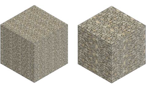
| Here is an example of the same object with the same material, but with the mapping of the material adjusted on the right-side object. |
| |
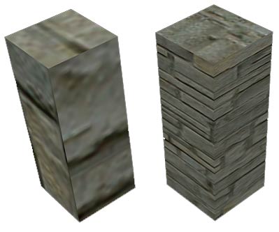 |
| By default, AutoCAD will apply the material as it sees fit. In this example above, the scale of the material is too small. To properly render the block, mapping is used to adjust and fine tune the material so that it looks the way you want it to appear. With a little knowledge of this command, you can make your renderings more realistic. |
| |
| Here are the commands needed for mapping your materials: |
| |
| COMMAND OR INPUT |
ICON |
DESCRIPTION |
| MATERIALMAP |
None |
Enter this on the command line to select mapping options via keyboard. |
| Planar Mapping |
 |
Maps individual faces of an object. |
| Box Mapping |
 |
Maps any solid object with controls for width, depth and height as well as rotation on all sides. |
| Sphere Mapping |
 |
Allows you to map any solid object, but uses rotation only. |
| Cylinder mapping |
 |
Maps a solid object with height and rotation only. |
|
| |
| Note also that the mapping icons are available on the render toolbar as a flyout. This lesson will explain each of the mapping options using the icons. To make the mapping toolbar appear, right-click on any toolbar and click on the mapping option in the list. |
| |
|
| |
| Start by selecting the menu option Tools > Palettes > Tool Palettes (or CTRL+3) and you will see a large palette appear that includes the default material library. |
| |
 |
The palette you have just opened contains all the default palettes in AutoCAD. You may or may not see the one you need when you open them up this way.
The palette you want for this exercise is the one called "Masonry - Materials Library".
If you don't see it, click in the area shown by the red box in the image to the left. This will display a list of all palettes available. Select the one needed for this exercise and it should then look like the one shown on the left. |
|
| |
| Start by drawing a box that is 120x120x240 high and do a Zoom>Extents. Set your visual style to Realistic (Menu: View > Visual Styles > Realistic). Switch to the SW ISO view. |
| |
| As shown , apply the material called "Masonry.Stone.Limestone.Rubble." to the box. Depending upon your settings it may look something like this in a default view. |
| |
 |
| |
| In this view, it looks like the 'rubble' of the material is made up of small rocks that you can't really see clearly. What you want to create in this exercise is a 'box of large visible rubble'. |
| |
We'll start with the BOX MAPPING icon  and then select the box and press enter. and then select the box and press enter. |
| |
| You should now see some new grips on your object (this are different from the grips that allow you to adjust the size of an object. |
| |
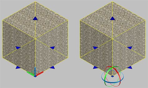 |
| The left box shows the default mapping grips available with the box option. |
|
The right box shows the added options when the rotate option (R) is selected on the command line. |
|
| |
| With the grips active, you will need to make the map larger by selecting the mapping grips one at time to make the material bounding box (in yellow) larger. Once you have finished moving a grip, click in the drawing space to release it. Note that there is one on the top as well (for height) as well as the four at the bottom. When you are happy with the look, press enter to end the command. Your new and improved box could look something like the one on the right: |
| |
 |
| |
| As you can see, the one on the right looks better than the default on the left. |
| |
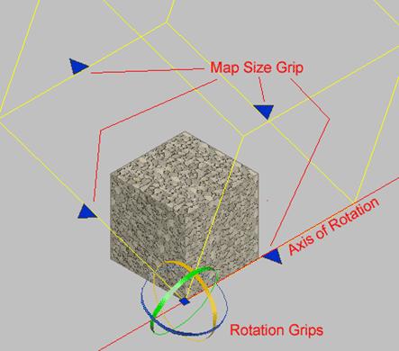
| Now start the Box Mapping option again, and type in R <ENTER> to invoke the Rotate option. You should now see the circular grips as shown two images above. To rotate the map, move your mouse over one of the circles and it will change colour. Click and you will be able to rotate the material around the axis you chose. |
| |
 |
| |
| From these simple options, you can control the look of any material on any object. Ultimately, the look of your final rendering is the choice of you - the designer. |
| |
| The image below shows the options below for the cylindrical and spherical mapping commands: |
| |
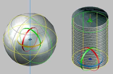 |
| The left image shows the options available with the spherical mapping command. Note that it is limited to Rotation and Moving. |
The right image shows the options of the cylindrical mapping command. It is limited to rotation and height adjustment. |
|
| |
| Try the two mapping methods shown above on a sphere and cylinder. Then try using the Box Mapping command on those objects. You may find that in common usage, the Box Mapping method will provide you with the most versatile options to acheive the look you want. |
| |
| Planar Mapping |
| |
| The other option not discussed yet is the PLANAR MAPPING command. It works a little differently than the others in that adjusts the material on one face only instead of the whole object. |
| |
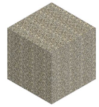
| Draw a cube 120x120x120. Apply a material to it that has some contrast to it so you can see the results clearly. |
| |
Start the Planar Mapping Command using this icon:  |
| |
| Instead of just selecting an object, press the Control Key as you click the box and you will see that only one face is highlighted. Click on the face that you want to map. From there, you will see that you have the same resize and rotate grips available to you, but will only affect the one face you selected. |
| |
|
| |