| Getting Started with AutoCAD |
| |
| More Modifying Commands |
| |
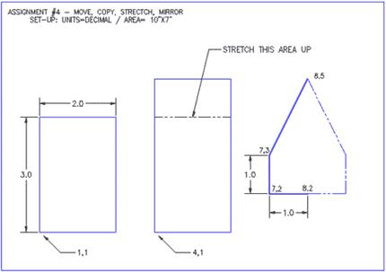
| In this assignment you will be adding some more common commands to your collection. All of these commands are ones that you will use on a regular basis. |
| |
| Command |
Keystroke |
Icon |
Menu |
Result |
| Move |
Move / M |
 |
Modify > Move |
Moves an object or objects |
| Copy |
Copy / CP |
 |
Modify > Copy |
Copies object(s) once or multiple times |
| Stretch |
Stretch / S |
 |
Modify > Stretch |
Stretches an object after you have selected a portion of it |
| Mirror |
Mirror / MI |
 |
Modify > Mirror |
Creates a mirror image of an object or selection set |
|
| |
| Turn on your Endpoint Osnap. |
| |
| This time draw the border first. Draw a 10" wide by 7" high rectangular border using any method. The bottom left corner must be at 0,0 |
| |
| Draw a 2" wide by 3" high rectangle using the RECTANGLE command. The bottom left corner must be at 0,0 |
| |
| Notice that the small rectangle and the border are overlapping each other at the bottom left of your drawing. What you want to do is move the small rectangle over 1" and up 1" so that it is away from the border. |
| |
| To do this, start the MOVE command by typing in either m or move <ENTER>. Select all the lines of the rectangle using one of the selection methods described earlier. Press <ENTER>. Now AutoCAD asks for a "base point or displacement". What it is needing is a reference point. Click on the bottom left corner of the rectangle. AutoCAD now asks for a 'second point of displacement'. What it needs to know now is how far you want to move it. This is a great time to use relative co-ordinates. In this case, you want to move it 1" over and 1" up. So type @1,1<ENTER> to achieve this. The rectangle will automatically move to its new location. |
| |
| Now you want to copy this rectangle 3" over to the right. The copy command is very similar to the move command. (The only difference is that the copy command leaves an original behind.) |
| |
| Start the COPY command. You will be asked to select objects. Select the rectangle you just moved. AutoCAD now needs the "base point or displacement" just like in the move command. Once again, select the bottom left corner of the rectangle. Once you've done this, you need to tell AutoCAD what the second point of displacement is. Since you want to move the rectangle over 3" to the right, type in @3,0 <ENTER> The rectangle has now been copied 3" over. |
| |
| But the rectangle is not as tall as the one in the sample drawing, the sample drawing's rectangle is 1" taller. To modify this, you'll use the stretch command. |
| |
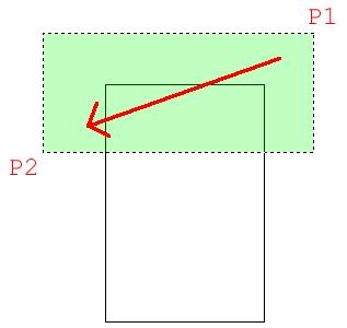
| Start the STRETCH command by typing S <ENTER>. AutoCAD now makes you select objects by using a crossing window or crossing polygon. You're going to use a crossing window. Remember from the Lesson 1-5 that you make a crossing window by creating it from the right to left. Left-click just a bit above and to the right of the top right hand corner of the new rectangle (P1). Move your crosshairs down and to the left until your (dotted) crossing window covers the top half of the rectangle completely and then left click again (P2). You'll see that the objects are highlighted now. Press <ENTER> to accept this. Next you're asked for that now familiar base point. Pick on the top left corner of the rectangle. Now give AutoCAD the second point of displacement. In this case, you want to stretch the rectangle 1" up, so type @0,1 <ENTER> to do this. The rectangle is now 1" taller. |
| |
 |
| |
| The goal when selecting objects to stretch is to draw the window over the vertices or points that you want to stretch. If you miss a corner, you will change the shape of the rectangle. So always be aware of which points need to be stretched. |
| |
| Next you want to draw the polygon on the right side. To do this, you will draw the three lines on the left side first and then mirror those lines over to the right side. Draw the 3 lines any way you like (hint: use absolute co-ordinates). |
| |
| Once they are drawn, begin the MIRROR command. Select the three lines (press <ENTER>) Now you are asked for the first point of the mirror line. With your endpoint Osnap turned on, pick the end of the line at 8,2. Now you are asked for the second point. Select the point on the line at 8,5. Once you've done this, AutoCAD wants to know if you want to delete the old objects. In this case you don't, so accept the default by pressing <ENTER>. Note: In general, the mirror line will be half-way between the object the you are mirroring and where you want it to be. |
| |
 |
| |
| The assignment is now complete. Review what you have done and practice on these commands. Save and print. |
| |
| More Modifying Commands |
| |
| Now it's time to learn a few more commands. Like all of the commands learnt so far, these too will be ones that you will use regularly. |
| |
| Here are the commands that you will be learning in this lesson. |
| |
| Command |
Keystroke |
Icon |
Menu |
Result |
| Rotate |
Rotate / RO |
 |
Modify > Rotate |
Rotates objects to a certain angle |
| Fillet |
Fillet / F |
 |
Modify > Fillet |
Creates a round corner between two lines |
| Chamfer |
Chamfer / CHA |
 |
Modify > Chamfer |
Creates an angled corner between two lines |
| Array |
Array / AR |
 |
Modify > Array |
Creates a repeating pattern of the selected objects |
|
| |
| Follow the steps shown carefully. As these commands require a little more input, make sure that you keep an eye on the command line. You will be asked to provide information throughout the commands. |
| |
| Start up AutoCAD and load the acad.dwt template like you have for the other lessons. |
| |
| Start by drawing a horizontal 10" X 7" border with the bottom left corner at 0,0 |
| |
| Draw a rectangle 1" wide by 3" tall with the bottom left corner at .75,.75 |
| |
| You are now going to rotate this rectangle 90° clockwise. |
| |
| Start the ROTATE command. AutoCAD asks you to select objects. Select all parts of the rectangle and press <ENTER>. Now you must indicate a 'base point'. Think of this as a pivot point around which the rectangle will rotate. In this example, you want to select the bottom right corner (remember to use your Osnap). Once you've selected the base point, the command line shows rotation angle or [Reference]:This means that 'Rotation angle' is the default, so type in the angle you want to rotate the object. Think about how AutoCAD measures angles. Looking at your rectangle and the one on the assignment sheet, you'll see that you want to rotate the rectangle clockwise or: -90 degrees. Enter that number and press <ENTER>. |
| |
Command: RO <ENTER>
Current positive angle in UCS: ANGDIR=counterclockwise ANGBASE=0
Select objects: <Select the Rectangle> 1 found
Select objects: <ENTER>
Specify base point: <PICK BOTTOM RIGHT CORNER OF THE RECTANGLE>
Specify rotation angle or [Reference]: -90 <ENTER> |
| |
| The rectangle is now been rotated -90 degrees from its original position. Picking different base points will give you different results. Undo the last command. Try a few different combinations of base points and angles to see what results you get. When you are done practicing, get the rectangle back to the position it was at the end of previous step. |
| |
| Make a COPY of the rectangle 2" above the first one (remember your relative co-ordinates). |
| |
| Now you're going to modify the second rectangle so that it has rounded corners. Start the FILLET command. Look at the command line. It will look something like this: |
| |
Command: F <ENTER> FILLET
Current settings: Mode = TRIM, Radius = 0.0000
Select first object or [Undo/Polyline/Radius/Trim/Multiple]: |
| |
| AutoCAD first shows you what the current fillet radius is (0.0000). This will be the last value that was used. Once it's changed, it will keep the new value in memory. The next line shows you what options you have in this command. Remember that the Capitol of each option selects that particular option. What you want to do is change the fillet radius to 3/8" (or .375). To do this you have to type R <ENTER>. When you type this AutoCAD will give the chance to enter a new fillet radius. At this point enter .375 and press <ENTER>. |
| |
| The fillet radius is now .375 (which is what you want). The default option is Select first object. Select the left side of the top rectangle (yes, the whole rectangle will highlight if you drew it as a rectangle). AutoCAD now asks you to select second object. Select the top line and AutoCAD will make a smooth round corner with a radius of .375. AutoCAD automatically ends the command at this point. |
| |
| Restart the FILLET command and do this to the remaining corners so that you have an object similar to the example. |
| |
| Copy the first rectangle to a point 4-1/2" above. Now you will use the chamfer command to give this rectangle sharp corners. |
| |
| Start the CHAMFER command. Look at the command line. It should look like this: |
| |
Command: CHA <ENTER> CHAMFER
(TRIM mode) Current chamfer Dist1 = 0.0000, Dist2 = 0.0000
Select first line or [Polyline/Distance/Angle/Trim/Method]: D <ENTER>
Specify first chamfer distance <0.5000>: .375 <ENTER>
Specify second chamfer distance <0.3750>: <ENTER>
Select first line or [Undo/Polyline/Distance/Angle/Trim/mEthod/Multiple]: <select one side of the rectangle> |
| |
| This is very similar to the fillet command. You have several options available. Want you want is an even 45 degree angle 3/8" in from the corner. Like the fillet command, you first have to tell AutoCAD what distance you want. To do this, type D to select the Distance option. The command line now looks like this: |
| |
| Specify first chamfer distance <0.5000>: .375 <ENTER> as your first distance.) The command line now asks for the second distance. AutoCAD will automatically change the default of the second distance to match the distance you entered for the first. |
| |
| Specify second chamfer distance <0.3750>: (Press <ENTER> to accept this) |
| |
| You will then be asked to Select first line. The chamfer command works just like the fillet command. Select the line on the left of the top rectangle. (Don't worry if the entire rectangle highlights.) When prompted to Select second line: select the top line. You will now have a perfect sharp corner at a 45 degree angle 3/8" in from the corner. Do this to the rest of the corners. |
| |
| Now look at the assignment sheet and notice the group of six rectangles on the bottom right. You could draw each one individually, but AutoCAD has a command that will allow you to draw one, and it will make the others. |
| |
| Create a rectangle that is 1/2" square with the bottom left corner at 6,1.5 (absolute points). |
| |
| Start the ARRAY command. Look at the dialog box shown below: |
| |
 |
| |
| When confronting a new dialog box, I recommend that you look for what is needed from the TOP DOWN to the bottom. This is a great example. |
| |
1. Choose the radio button for "Rectangular Array". This will array the object in a row/column arrangement.
2. Next select the object you want to array, by picking on the button in the top right corner. (Press enter when done)
3. Enter the number of rows (going across the page) and column (running up and down the page).
4. Enter the Row offset. This is this from the bottom left of the original rectangle, to the bottom left of where the first copy will go.
5. Enter the Column offset
6. Pick the Preview button to see the array before committing. |
| |
 |
| |
| If the array is correct (check the sample drawing), press the "Accept" button. If you need to change anything, press the "Modify" button, make your changes in the dialog box and preview again. |
| |
| Now you are going to use the ARRAY (polar) command to create the shape in the top right corner of the assignment. |
| |
| Start by making a CIRCLE with a center point of 7.5,5.5 and a diameter of 1.5 Next make a LINE from the center of the circle going 1" to the right (remember your relative input and Osnaps). |
| |
| Start the ARRAY command. When asked to select objects, pick the line you just drew. |
| |
 |
| |
| Examine the dialog box above. Remember to start from the TOP. In this case, you have to select your objects and select a Center Point for the array. (Select the center of the circle.) |
| |
| Save and print your drawing. |
| |
|
| |